

 |
| Today we measured the magnetic field of a current carrying wire with N loops. |
 |
From our data we see that as the number of loops go up the magnetic field gets stronger . But as a whole B/NI is decreasing, which we then compare to Inductance to say that the inductance is growing. |


 |
| Here we have a DC motor being powered by a 3v battery at a steady current. with a magnetic field perpendicular to a to the current giving it a force to turn. |
 |
| Here we can see the magnetic field surrounding the bar magnet. |
 |
| Here we see how the magnetic flux of a closed surface is similar to gauess law for electric flux. integral of b*dA =0 |
 |
| The unit for the magnetic flux is the webber. |
 |
| Here we can see that the right hand rule still applies. and that force is equal to F=qVx B |
 |
| A simple sample problem where we have a known magnetic field velocity and theta |
 |
| A particle in a magnetic field is being affected by a magnetic force. notice how the force propels it forward. and the electric force bring it down, |
 |
| A Heat Gun |
 |
| This shows how in a magnetic field a particle will tend to move in a circle clockwise or counter clockwise depending on charge magnetic field and direction of velocity. |
 |
| The velocity of the charge is also the current though the wire so the wire experiences a force up or down. |
 |
| This explains the video we just saw that the current I through a wire some length L will experience a force if there is a perpendicular magnetic force. |
 |
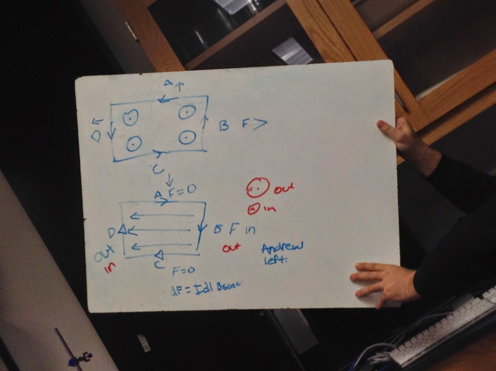
| all the forces around the loop cancel out. |
 |
| The force on a hemisphere from a constant magnetic field can be found by splitting wire into tiny pieces of dL length. L=rtheta. |
 |
| Here we have a breadboard circuit with an led and resistor, the led acts as a diode meaning it only allows current to flow one way. |
 |
| Here we have a switch which is always in the open state, |
 |
| a schematic with a transistor that will act too amplify our signal current/collector. |
 |
| here we have an electron gun and we can see how moving the horizontal deflection plates and vertical deflection plates move the particle horizontal or vertical respectively. |
 |
| Here we have an electronn passing through two plates a distance d apart with voltage V a distance L. F=qE E=Vd F=qVd=ma a=qv/md and therefore we can find velocity after some time or distance. |
 |
| Our work of the above problem.! |
 |
| here we have a picture of our speaker connected to our function generator. |
 |
| A sine wave function The y axis is measure in amps/division and the horizontal is measure in time/div |
 |
| Square Wave |
 |
 |
| we learned that for capacitor in series the charge is conserved and that capacitors in parallel have the same voltage drop across one another. |
 |
| we also proved theoretically by using the definition of current flow and relating it to capacitance that qc= q0 e(-t/RC), and V=Vo e^(-t/rc) |
 |
| Here we have applied a best fit to the graph and shown experimentally the rate at which capacitors discharge and charge. Where the constant C is equal to 1/rc. |
 |
| This is the derivation for Kirchhoff's rules in series and in parallel. |
 |
| Next we were thought how to read resistors and how to calculate or see their uncertainty. |